multiplexer and demultiplexer
multiplexer
MULTIPLEX OPERATION
The simultaneous transmission of several signals along a single without any loss of identity of an individual signal. The various signals are input to a multiplexer that is used to allocate a transmission path to the input according to a particular parameter of the signal (like Frequency, Time or Statistics).
The original signals are reconstructed at the receiver by a demultiplexer that is operated so as to synchronize with mutiplexer. The transmission path may use any suitable medium, such as wire, waveguide, glass fibers or radiowaves. The communication channel chosen is termed a multiplex channel.
Multiplex operation is done in three manners and they are
(a) Space Division Multiplexing OR Statistical Multiplexing
(b) Time Division Multiplexing
(c) Frequency Division Multiplexing
(a) Space Division Multiplexing or Statistical Multiplexing:
In communications, a method of sharing a transmission channel by using statistical techniques to allocate resources. So many individual communication lines are grouped together to form a communication channel A statistical multiplexer can analyze traffic density and can dynamically switch to a different channel pattern to speed up the transmission. At the receiving end; the different signals are separated into individual lines. So it permitted the individual connection to each user.
Like in telephone exchange, a multi cable is used to packed many subscriber’s lines and near the subscriber’s premises, these are separated into individual streams.
Generally this method is used in base band transmission (for short distance).
(b) Frequency Division Multiplexing:
In this type of communication, A bandwidth (which can be transmitted by communication channel) is divided into many smaller logical channel with each channel having a small bandwidth: In this method the individual carrier frequency is required for each modulating signal (like speech) and these carriers are modulated according to heir modulating signals.
In figure A bandwidth is 100 KHz and it has 10 individual signals, which are demodulated and transmitted as a single band of 100 KHz and at the receiving and it is demodulated into 10 individual signals this process is normally used in Radio Broadcasting.

(c)Time-Dlvlelon Mutlplexing:
In this method, the available time is divided into available input signals (i.e. quantum of time is allocated to each signal during a definite interval). It seems that all the message are sent in parallel but infect a sample of one message is transmitted within its allocated time and a sample of another message after that so all the samples are transmitted sequentially but very fast and all the samples of any one message is reassembled at receiving and so each user seems like all processes are done simultaneously

Time-Division Multiplexing
Multiplexer
“Multiplexer means many sources (inputs) with one Destination (output) so it is used as a data selector circuit.”
When we have fed any two control bits like 00. So first AND gate is enable while all the other AND gates are disabled. So in this case only I0 is able to transmit the number at output. I0 is low then Y (output) is low & I0 is high then Y is high. This makes the output Y =l0
Now the only one AND gate is enabled (i.e. t makes the output with the help of input I0 ) and all the other gates are disabled (So their inputs have not any output) and all the outputs of all gates are ORED by an OR gate so we have only one output out of four inputs.
In multiplexer, At any time there are so many inputs but only one output. This concept is broadly utilized in the transmission of signals or in communications where so many signals are transmitted in the form of one signal while at other receiver end it is demultiplexed at (i.e. one input with so many output).
Applications of Multiplexer:
(1) It is used as a parallel to serial converter in serial communication.
(2) One practical example of Multiplexer is memory addressing for the video memory in which the memory is shared to both the CPU (8088) and the CRT controller (6845), it is shown in figure. Here for each address bit a 2 to 1 multiplexer is required in which the select input A=0, then CPU’s address is selected and A=1. Then CRT controller’s address is selected.

Video Memory Multiplexing
Demultiplexer
Demultiplexer means only one source (input) with many destinations (outputs) so it is used as a data discriminator circuit.” It is a logic circuit of one input with many outputs& control signals decide that which one output will be enabled &which data bit is transmitted.
Here only one input I0 is given and four output Y0 Y1 Y2 and Y3 are shown in figure

1 to 4 Demultiplexer
This input bit is transmitted to data bit of the all outputs but control bits decide one output bit like is
(1) Control bit AB=01 then the second AND gate is enabled and other AND gates are disabled so the input bit I0 is transmitted only to the Y, output, thus given Y1=I0
(2) Control bit AB-11 then fourth AND gate is enabled and other AND gates are disabled so the input bit I0 is transmitted only to the Y3 output. Thus giving Y3=I0 and all other output like Y0 Y1 Y2 are in low state.
This concept is utilized in these logic circuit which are used at the receiver end to differentiate the one signal into many like a telephone line. At DP so many subscribers are connected with this DP but the transmission line contained only with one cable for transmitting many signals so with the help of multiplexer these many signals are converted into one and transmitted.
Again at DP, this one signal is divided into many individual signals by using the dimultiplexer circuit thus in this manner we can communicate with telephone.
Applications of Demultiplexer:
(1) It is used as serial to parallel converter in parallel communication.
(2) One example of Demultiplexer is in serial to parallel conversion of data in the floppy controller or Hard disk controller during a read operation which is shown in

Serial to Parallel Conversion

Multiplexing and Demultiplexing is used in telephonic talk
DECODER
In decoder, there are N input lines and 2N output lines. At a time only one output line is active and this output line is decided by input bit pattern, is shown in figure

Decoder Block Diagram
So for each input bit pattern, one output line is there, it is shown in Table.
Applications of Decoder:
(1) It is used as command decoder.
(2) It is used as a Port address decoder.
(3) ft is used as a Device number decoder.
(4) It is used as a Binary to decimal converter which is shown in figure

Decoder

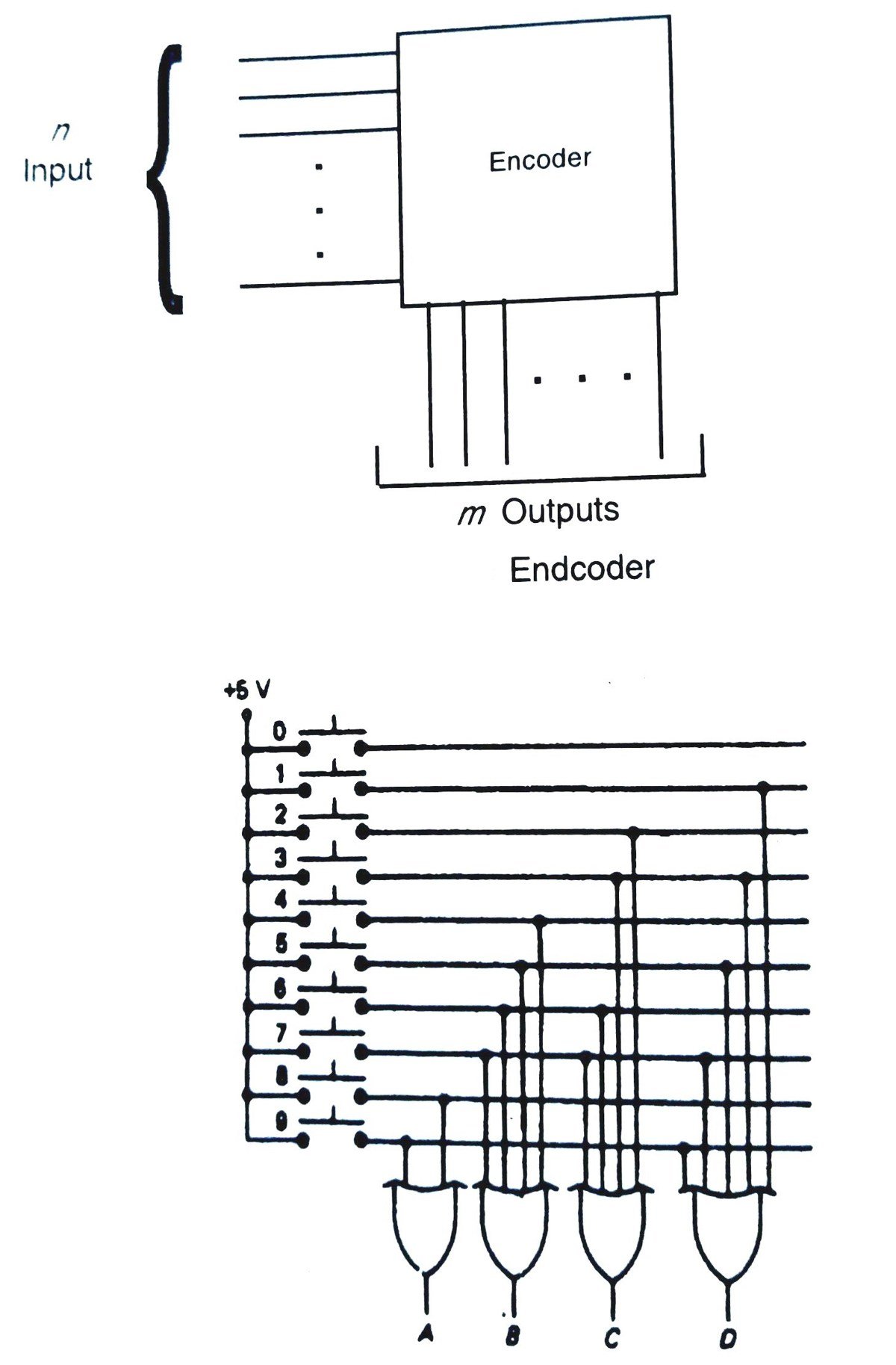
ENCODER
It is basically the reverse of a decoder so it has 2N inputs and N outputs. At a time only one of the input is active and this active input is recognized by a bit pattern on the output lines.

Application of Encoder:
(1) It is used to identify the active device signal out of multiple devices/signals.
(2) Practically it is used as a keyboard encoder where a key has been pressed and generate a corresponding bit code. A very similar example is shown in figure of Decimal to Binary encoder